
Venturi
Click the following subjects to be taken to them within this page:
- Classical Venturi Diagram and description
- Classical Venturi Dimensional Data
- Flow Rate Capacities for Classical Venturi
- Low Loss Venturi Diagram and description

Venturis come in several forms: Classical, Low Loss and Universal Style. Venturis 6" pipe size and smaller may also be manufactured from barstock to create a weldless design.
This primary element produces a differential, which is proportional to the square of the flow rate through the device, utilizing static pressure sensed at the inlet tap and the throat tap.
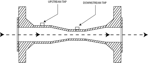
The venturi shall be fabricated in accordance with A.S.M.E. specifications and recommendations. The inlet section shall consist of a straight pipe section of like diameter to the preceding line pipe, and an entrance cone with an A.S.M.E. specified 21 degree angle of convergence. The throat shall be a straight cylindrical section at least 0.5 times the throat diameter. The outlet section shall be an exit cone with an A.S.M.E. specified 15 degree angle of divergence.
The venturi will be furnished with two pressure sensing taps; one in the straight inlet pipe section (upstream tap) and one in the throat section (downstream tap). There shall be no annular chanbers or slots within the venturi.
The venturi body will be constructed of either rolled ASTM A 285 C carbon steel or the end-users choice, and the throat will be constructed of either T-304 stainless steel of the end-users choice.
The venturi shall have a discharge coefficient that is constant over the normal range of flow; independent of Beta Ration or line size.
The venturi shall have an uncalibrated accuracy of + or - 0.75% of actual flow for the range specified.
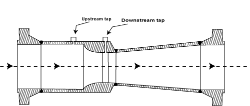
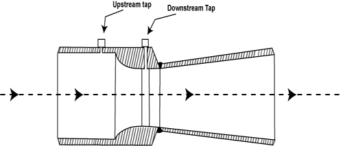
Classical Venturi
The classical (ASME) venturi comes in both short form and long forms.
Flanged Connections
Butt-welded Connections
The long form has the benefit of having less permanent pressure loss
while the short form uses less space in the piping system. The classical venturi creates a lower differential pressure than the low loss venturi and
can be ideal for slower flows. The included angles for the inlet and outlet comes are as follows:
Upstream: 10.5 degrees
Downstream: 3.75 degrees
Back to top
Dimensional Data
| Dimensional Data For Short Form Classical (ASME) Venturis | ||||||
| Pipe Size | Beta Ratio | Length/Inches | Weight in LBS | |||
| Flanged Ends | Weld Ends | Weld Ends | 150# Flanged Ends | 300# Flanged Ends | ||
| 3" | 0.35 | 24 | 24 | 22 | 48 | 65 |
| 0.55 | 20 | 20 | 20 | 45 | 62 | |
| 0.70 | 16 | 16 | 16 | 30 | 55 | |
| 6" | 0.35 | 34 | 37 | 55 | 23 | 133 |
| 0.55 | 27 | 30 | 52 | 20 | 130 | |
| 0.70 | 22 | 25 | 50 | 88 | 128 | |
| 8" | 0.35 | 45 | 48 | 100 | 160 | 216 |
| 0.55 | 36 | 40 | 85 | 145 | 201 | |
| 0.70 | 29 | 33 | 78 | 138 | 194 | |
| 10" | 0.35 | 56 | 60 | 160 | 246 | 322 |
| 0.55 | 45 | 50 | 135 | 221 | 297 | |
| 0.70 | 37 | 42 | 115 | 201 | 277 | |
| 12" | 0.35 | 67 | 73 | 278 | 406 | 508 |
| 0.55 | 54 | 60 | 226 | 354 | 456 | |
| 0.70 | 44 | 50 | 185 | 313 | 415 | |
| 14" | 0.35 | 74 | 80 | 346 | 516 | 674 |
| 0.55 | 60 | 66 | 295 | 465 | 623 | |
| 0.70 | 49 | 55 | 250 | 420 | 528 | |
| 16" | 0.35 | 86 | 92 | 438 | 624 | 878 |
| 0.55 | 70 | 76 | 394 | 580 | 834 | |
| 0.70 | 57 | 63 | 358 | 544 | 798 | |
| 18" | 0.35 | 98 | 106 | 565 | 805 | 1125 |
| 0.55 | 78 | 86 | 445 | 685 | 1005 | |
| 0.70 | 64 | 72 | 390 | 630 | 905 | |
| 20" | 0.35 | 108 | 118 | 734 | 1044 | 1384 |
| 0.55 | 86 | 96 | 630 | 940 | 1280 | |
| 0.70 | 72 | 82 | 536 | 846 | 1186 | |
| 24" | 0.35 | 130 | 142 | 958 | 1378 | 1938 |
| 0.55 | 104 | 116 | 820 | 1240 | 1800 | |
| 0.70 | 86 | 98 | 706 | 1126 | 1686 | |
| 30" | 0.35 | 164 | 180 | 1660 | O.A. | O.A. |
| 0.55 | 132 | 147 | 1415 | O.A. | O.A. | |
| 0.70 | 107 | 122 | 1245 | O.A. | O.A. | |
| 36" | 0.35 | 197 | 215 | 2418 | O.A. | O.A. |
| 0.55 | 158 | 176 | 2080 | O.A. | O.A. | |
| 0.70 | 130 | 148 | 1810 | O.A. | O.A. | |
| 42" | 0.35 | 222 | 240 | 3318 | O.A. | O.A. |
| 0.55 | 186 | 204 | 2820 | O.A. | O.A. | |
| 0.70 | 150 | 168 | 2341 | O.A. | O.A. | |
| 48" | 0.35 | 264 | 288 | 4510 | O.A. | O.A. |
| 0.55 | 212 | 236 | 3744 | O.A. | O.A. | |
| 0.70 | 174 | 198 | 3108 | O.A. | O.A. | |
Back to top
Flow Rate Capacities for Classical (ASME) Venturis
| Flow Rate Capacities for Classical (ASME) Venturis | |||||||
| Pipe Size | Beta Ratio | Throat Bore | Flow Rates in GPM of Water @ 60 deg. F | ||||
| Diffential in Inches W.C. | |||||||
| 30" | 50" | 100" | 200" | 300" | |||
| 1" | 0.35 | 0.3671" | 4 | 5.2 | 7.3 | 10.5 | 12.8 |
| 0.55 | 0.5769" | 10 | 13.5 | 19.2 | 27.3 | 33.5 | |
| 0.70 | 0.7343" | 19 | 24.1 | 34.3 | 48.7 | 60.4 | |
| 2" | 0.35 | 0.7234" | 16 | 20.3 | 29.0 | 41.0 | 50.0 |
| 0.55 | 1.1368" | 41 | 53.0 | 75.0 | 108.0 | 132.0 | |
| 0.70 | 1.4469" | 73 | 94.0 | 135.0 | 191.0 | 235.0 | |
| 3" | 0.35 | 1.0738" | 35 | 45.0 | 64.0 | 91.0 | 112.0 |
| 0.55 | 1.6874" | 91 | 117.0 | 168.0 | 238.0 | 292.0 | |
| 0.70 | 2.1470" | 163 | 211.0 | 298.0 | 422.0 | 516.0 | |
| 4" | 0.35 | 1.4091" | 62 | 80.0 | 113.0 | 160.0 | 195.0 |
| 0.55 | 2.2140" | 159 | 205.0 | 290.0 | 410.0 | 502.0 | |
| 0.70 | 2.8180" | 281 | 363.0 | 514.0 | 726.0 | 890.0 | |
| 5" | 0.35 | 1.7670" | 97 | 125.0 | 177.0 | 250.0 | 307.0 |
| 0.55 | 2.7760" | 250 | 322.0 | 456.0 | 645.0 | 789.0 | |
| 0.70 | 3.5330" | 442 | 571.0 | 807.0 | 1140.0 | 1400.0 | |
| 6" | 0.35 | 2.1230" | 140 | 181.0 | 256.0 | 362.0 | 445.08 |
| 0.55 | 3.3360" | 361 | 465.0 | 658.0 | 931.0 | 1140.0 | |
| 0.70 | 4.2450" | 640 | 825.0 | 1165.0 | 1650.0 | 2020.0 | |
| 8" | 0.35 | 2.7930" | 243 | 315.0 | 445.0 | 625.0 | 770.0 |
| 0.55 | 4.3900" | 625 | 805.0 | 1140.0 | 1610.0 | 1975.0 | |
| 0.70 | 5.5870" | 1105 | 1425.0 | 2020.0 | 2855.0 | 3500.0 | |
| 10" | 0.35 | 3.5070" | 380 | 490.0 | 690.0 | 980.0 | 1200.0 |
| 0.55 | 5.5110" | 975 | 1260.0 | 1780.0 | 2515.0 | 3080.0 | |
| 0.70 | 7.0140" | 1725 | 2230.0 | 3150.0 | 4455.0 | 5455.0 | |
| 12" | 0.35 | 4.2000" | 540 | 700.0 | 995.0 | 1400.0 | 1720.0 |
| 0.55 | 6.6000" | 1400 | 1800.0 | 2550.0 | 3610.0 | 4420.0 | |
| 0.70 | 8.4000" | 2475 | 3195.0 | 4520.0 | 6390.0 | 7825.0 | |
| 14" | 0.35 | 4.6380" | 660 | 855.0 | 1210.0 | 1710.0 | 2095.0 |
| 0.55 | 7.2880" | 1705 | 2200.0 | 3110.0 | 4400.0 | 5385.0 | |
| 0.70 | 9.2750" | 3015 | 3895.0 | 5510.0 | 7790.0 | 9540.0 | |
| 16" | 0.35 | 5.3380" | 875 | 1135.0 | 1600.0 | 2265.0 | 2775.0 |
| 0.55 | 8.3880" | 2255 | 2915.0 | 4120.0 | 5825.0 | 7135.0 | |
| 0.70 | 10.6750" | 4000 | 5160.0 | 7300.0 | 10320.0 | 12640.0 | |
| 18" | 0.35 | 6.0380" | 1225 | 1450.0 | 2050.0 | 2900.0 | 3550.0 |
| 0.55 | 9.4880" | 2890 | 3730.0 | 5270.0 | 7455.0 | 9130.0 | |
| 0.70 | 12.0750" | 5110 | 6600.0 | 9340.0 | 13200.0 | 16170.0 | |
| 20" | 0.35 | 6.7380" | 1400 | 1800.0 | 2550.0 | 3610.0 | 4420.0 |
| 0.55 | 10.5880" | 3595 | 4640.0 | 6560.0 | 9280.0 | 11370.0 | |
| 0.70 | 13.4750" | 6370 | 8220.0 | 11630.0 | 16440.0 | 20130.0 | |
| 24" | 0.35 | 8.1380" | 2039 | 2630.0 | 3725.0 | 5270.0 | 6450.0 |
| 0.55 | 12.7880" | 5240 | 6770.0 | 9575.0 | 13540.0 | 16580.0 | |
| 0.70 | 16.2750" | 9290 | 11990.0 | 16960.0 | 24000.0 | 29400.0 | |
| 30" | 0.35 | 10.2380" | 3230 | 4170.0 | 5895.0 | 8335.0 | 10200.0 |
| 0.55 | 16.0880" | 8300 | 10700.0 | 15150.0 | 21400.0 | 26250.0 | |
| 0.70 | 20.4750" | 14700 | 18980.0 | 26800.0 | 38000.0 | 46500.0 | |
| 36" | 0.35 | 12.3380" | 4690 | 6050.0 | 8560.0 | 12100.0 | 14800.0 |
| 0.55 | 19.3880" | 12050 | 15550.0 | 22000.0 | 31100.0 | 38100.0 | |
| 0.70 | 24.6750" | 21350 | 27570.0 | 39000.0 | 55100.0 | 67500.0 | |
| 48" | 0.35 | 16.5380" | 8420 | 10800.0 | 15400.0 | 21750.0 | 26600.0 |
| 0.55 | 25.9880" | 21650 | 28000.0 | 39500.0 | 56000.0 | 68500.0 | |
| 0.70 | 33.0750" | 38400 | 49500.0 | 70000.0 | 99000.0 | 121300.0 | |
Beta Ratios are based on Standard Weight Pipe.
This capacity chart is provided as a reference tool only. Contact factory with your
flow conditions for exact rate calculations.
Back to top
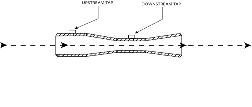
Low Loss Venturi
The Low Loss Venturi is designed to create a low permanent pressure loss of approximately 5%.
Flanged Connections
Butt-welded Connections
The Low Loss Venturi, however, creates a higher differential
pressure which can be an issue with low pressure applications. The included angles for low loss venturis are as follows:
Upstream radius: D/4
Downstream: 10 degrees