Navigation Bar

Print it out to a .pdf

Paddle Type Orifice Plate


General Notes:


  1. Orifice plates constructed in accordance with AGA report No. 3 / API 14.3 / ISA RP3.2
  2. Orifice plate shall be polish finished to 32 to 16 micro-inches RMS (symbol 32√ to 16√ )
  3. The orifice plate shall be flat to within 0.010" per inch of dam height. [(D-d)/2]
  4. The upstream edge of the orifice bore shall be free of nicks and shall be square and
    sharp so it will not appreciably reflect a beam of light when viewed without magnification.
  5. Restriction orifice plates (RO & FO) tag#'s do not require a downstream bevel. Therefore t = T.
Line Size A, Outside Diameter (5) Ledge Width L.Handle Width W. Handle Width Line Size
150# 300# 400# 600# 900# 1500# 2500#
0.50" 1.875 2.125 2.125 2.125 2.500 2.500 2.750 0.010 4.000 1.000 0.50"
0.75" 2.250 2.625 2.625 2.625 2.750 2.750 3.000 0.015 4.000 1.000 0.75"
1" 2.625 2.875 2.875 2.875 3.125 3.125 3.375 0.015 4.000 1.000 1"
1.5" 3.375 3.750 3.750 3.750 3.875 3.875 4.625 0.015 4.000 1.000 1.5"
2" 4.125 4.375 4.375 4.375 5.625 5.625 5.750 0.030 4.000 1.000 2"
2.5" 4.875 5.125 5.125 5.125 6.500 6.500 6.625 0.030 4.000 1.000 2.5"
3" 5.375 5.875 5.875 5.875 6.625 6.875 7.750 0.030 4.000 1.000 3"
4" 6.875 7.125 7.000 7.625 8.125 8.250 9.250 0.062 4.000 1.000 4"
5" 7.750 8.500 8.375 9.500 9.750 10.000 11.000 0.062 4.000 1.000 5"
6" 8.750 9.875 9.750 10.500 11.375 11.125 12.125 0.062 4.000 1.000 6"
8" 11.000 12.125 12.000 12.625 14.125 13.875 15.250 0.125 6.000 1.500 8"
10" 13.375 14.250 14.125 15.750 17.125 17.125 18.750 0.125 6.000 1.500 10"
12" 16.125 16.625 16.500 18.000 19.625 20.500 21.625 0.125 6.000 1.500 12"
14" 17.750 19.125 19.000 19.375 20.500 22.750 --- 0.250 6.000 1.500 14"
16" 20.250 21.250 21.125 22.250 22.625 25.250 --- 0.250 6.000 1.500 16"
18" 21.500 23.375 23.250 24.000 25.000 27.625 --- 0.250 6.000 1.500 18"
20" 23.750 25.625 25.375 26.750 27.375 29.625 --- 0.375 6.000 1.500 20"
22" 26.000 27.750 27.500 28.875 --- --- --- 0.375 6.000 1.500 22"
24" 28.125 30.375 30.125 31.000 32.875 35.500 --- 0.375 6.000 1.500 24"
30" 34.625 34.875 37.250 38.125 --- --- --- 0.375 6.000 1.500 30"
Unless otherwise specified, dimensions are in inches. Tolerances are:
Fractions Decimals Angles
± 1/16" .xx ± .06" ± 1°
.xxx ± .010
TABLE 2
Tolerances per ISA RP3.2
Bore Dia. inches Dia. Tolerance ± inches
less than 0.25000 0.0003
0.2501 - 0.3750 0.0005
0.3571 - 0.5000 0.0006
0.5001 - 0.6250 0.0008
0.6251 - 0.7500 0.0009
0.7501 - 0.8750 0.0010
0.8751 - 1.0000 0.0012
1.0001 - 1.2500 0.0014
1.2501 - 1.5000 0.0017
1.5001 - 5.0000 0.0025
Over 5.000 0.0005 per inch of dia.
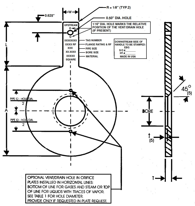
TABLE 1
Bore Dia. inches Hole Dia. inches
1.000 - 3.500 3/32
3.500 - 5.000 1/8
5.000 - 6.750 3/16
6.751 - 8.375 1/4
8.376 - 10.000 5/16
10.001 - 11.625 3/8
11.626 - 13.250 7/16
Over 1 1/2